Damage-tolerant CFRP foam sandwich structures for aircraft construction

© Fraunhofer IMWS
Sandwich structure consisting of closed-cell polymer rigid foam and CFRP face sheets (left), light microscope image of the face sheet-core interface with resin-filled foam cells (right).
© Fraunhofer IMWS
3-point bending test with hard foam test specimen notched on one side (SENB).
© Fraunhofer IMWS
Results of fracture toughness for different PMI rigid foam types.

The sandwich construction with a rigid polymer foam core and carbon fibre-reinforced plastic cover layers offers high bending stiffness at low weight. However, the thin cover layers are susceptible to damage from low impact energies such as hail or falling tools. The SANDWICH² project within the aeronautics research programme LuFo V focuses on investigating and optimising the damage tolerance of such foam sandwich structures, in particular through a microstructure and mechanism-based assessment method. The Fraunhofer Institute for Microstructure of Materials and Systems IMWS is part of the research consortium and responsible for this research.

Evaluation methods for demonstrating the damage tolerance of foam sandwich structures

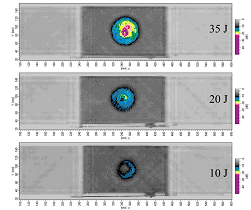
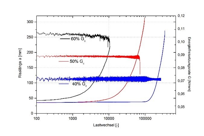
In the context of damage tolerance design for foam sandwich structures, a reliable assessment method is required to predict the propagation of local damage under service loads. Here, an interface crack between the differently stiff materials CFRP laminate in the top layer and rigid polymer foam in the core is considered (see Figure 1). Fracture mechanics parameters are experimentally evaluated to determine crack fracture toughness and crack propagation parameters. Special attention is paid to characterising the material mechanical behaviour of the foam core, as it is the weakest component and exhibits residual stresses due to manufacturing. A finite element analysis enables the prediction of the residual load-bearing capacity and residual service life, taking into account defined cover layer delamination. Validation is carried out using tests on structures close to the component.

Fracture mechanics characterisation of the foam core

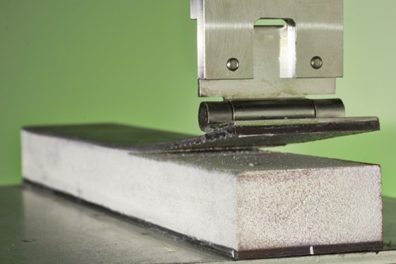
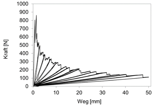
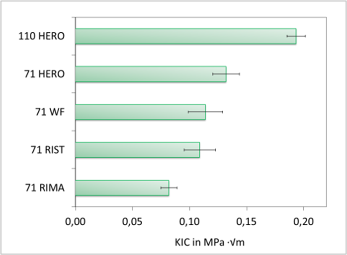
To characterise the fracture mechanics of the closed-cell PMI rigid foam ROHACELL®, appropriate tests were first carried out on coupon specimens. Among other things, the 3-point bending test with a single edge notched bend (SENB) specimen was used to determine the fracture toughness KIC under Mode I load for foams of different cell size and density. It was found that the fracture toughness for foams with approximately the same density of, for example, 75 kg/m³ increases with increasing cell size (from 71RIMA with approx. 50 µm to 71WF with approx. 600 µm mean cell diameter, see Figure 3). In contrast, the PMI rigid foam HERO with toughness-optimised basic formulation shows increased fracture toughness characteristics despite comparatively small cell sizes (see Figure 2). For foams with a higher density, the determined fracture toughness values also generally increase significantly (from 71HERO with 75 kg/m³ to 110HERO with 110 kg/m³).

© Fraunhofer IMWS
C-scans from air-coupled ultrasound examinations show impact damage (coloured marking) at 35 J, 20 J, 10 J with low velocity < 5 m/s [Joh16].
© Fraunhofer IMWS
Single Cantilever Beam (SCB) test to determine the critical energy release rate of the interface crack under dominant Mode I load.
© Fraunhofer IMWS
Force-displacement curve of a quasi-static SCB test with several loading and unloading cycles.

Investigation of damage propagation in the sandwich structure

In the case of impact loading, localised face layer delamination can occur, affecting the integrity of the sandwich structure. Air-coupled ultrasonic examinations are used to identify and evaluate such damage. Following experimental impact testing in a drop-weight test facility in the laboratory, these examinations allow non-destructive detection of the damage and quantitative assessment of its spatial extent. Figure 3 shows typical images (C-scans) of impact-damaged sandwich structures.

For the fracture-mechanical assessment of the propagation of such impact damage under both static and cyclic operating loads, the relevant fracture-mechanical characteristic values for the interface crack between the face layer and the core must be determined. For this purpose, specimens are used in which cover layer detachments have been deliberately created, for example by placing a PTFE film between the cover layer and the core. Subsequently, fracture mechanical parameters such as crack fracture toughness and crack propagation parameters are determined under quasi-static and cyclic loading for different crack opening modes. Mode I load under global tensile stress is usually the most critical load case.

To determine the critical energy release rate under Mode I load, the Single Cantilever Beam (SCB) test setup is used. Here, the unilaterally detached cover layer is pulled off vertically from the core. The test procedure is exemplified by Figure 4, including the force-displacement curve in a quasi-static SCB test. Several loading cycles are performed, with the specimen being completely unloaded in the intermediate at predefined maximum deflections. This allows additional information on crack length-dependent influencing variables to be obtained. The determination of the critical energy release rate Gc is based on the Compliance Calibration Method (CC). For this purpose, the crack lengths are determined for a certain number of force-displacement measuring points. The deformation of the SCB sample in the test is continuously recorded with high-resolution optical cameras in order to measure the crack lengths afterwards. Typically, crack propagation within the first foam cell layer occurs along the interface between the face layer and the core.

For the characterisation of the fatigue behaviour, classical fatigue tests are performed either under constant stress or displacement amplitude. However, the energy release rate (EFR) in the SCB test would increase significantly with increasing crack length until it exceeds the critical static value of EFR and leads to unstable crack growth. As a result, only a few measured values in the range of stable crack growth could be recorded. To circumvent this problem, the constant G method is used as an alternative way to determine crack growth under cyclic loads with almost constant stresses at the crack tip.

The constant G method is based on the analytical determination of the relationship between the compliance of the loaded specimen and the crack length. This makes it possible to calculate the energy release rate during the ongoing test from the force and displacement signals of the testing machine for each load cycle and keep it constant while the crack length continuously increases (see Figure 5). This allows the acquisition of a larger number of measured values in the area of stable crack growth and thus a reliable determination of fatigue crack growth using Paris' law [Par99].

The combination of ultrasonic investigations for the detection and evaluation of impact damage and fracture mechanics tests for the characterisation of the crack behaviour under different loads and crack opening modes enables a comprehensive evaluation of the damage tolerance and fatigue properties of sandwich structures. The knowledge gained serves as a basis for the development and optimisation of reliable and resilient lightweight structures.


[Joh16] John M., Schlimper R., Mudra Chr.: Deformation and failure behavior of pre-damaged foam-core sandwich structures in a four-point bending configuration, Proceedings of ECCM17, Juni 2016, München

[Par99] Paul C Paris, Hiroshi Tada, J.Keith Donald: Service load fatigue damage — a historical perspective, International Journal of Fatigue, Volume 21, Supplement 1, 1999

© Fraunhofer IMWS
Crack length as a function of the number of load cycles

Die Konstant-G-Methode basiert auf der analytischen Bestimmung des Zusammenhangs zwischen der Nachgiebigkeit der belasteten Probe und der Risslänge. Dadurch ist es möglich, die Energiefreisetzungsrate während des laufenden Versuchs aus den Kraft- und Wegsignalen der Prüfmaschine für jeden Lastzyklus zu berechnen und konstant zu halten, während die Risslänge kontinuierlich zunimmt (siehe Abbildung 5). Dies ermöglicht die Erfassung einer größeren Anzahl von Messwerten im Bereich des stabilen Risswachstums und somit eine zuverlässige Bestimmung des Ermüdungsrisswachstums mithilfe des Paris-Gesetzes [Par99].

Durch die Kombination von Ultraschalluntersuchungen zur Detektion und Bewertung von Impaktschäden sowie bruchmechanischen Tests zur Charakterisierung des Rissverhaltens unter verschiedenen Belastungen und Rissöffnungsmoden wird eine umfassende Bewertung der Schadenstoleranz und Ermüdungseigenschaften von Sandwichstrukturen ermöglicht. Die gewonnenen Erkenntnisse dienen als Grundlage für die Entwicklung und Optimierung von zuverlässigen und belastbaren Leichtbaukonstruktionen.